I am never good at documenting my works, there is no drawn plans, even if there is one, I would not be able to strictly adhere to it, the design will change as the work progress as I have to work within the confine of the materials that I can obtain, and the limited tools that I have. The best that I can illustrate were some pictures that I took along the built:
The camera stripped-down to skeletal remains, the black casing on the left will play a vital part for mating the cooling module with the camera. It will also house the tempreature/humidity guage, mini PCB for bulb control and also fan speed controller.

This is the real business end, not much room to insert the copper cold finger between the CMOS & the PCB, only 1mm thick.

Cooling module, the peltier element is sandwiched firmly between the heat sink and the copper cold finger by a carbon composite panel. on the right pic, I applied as much insulating materials as the space can afford.

Worth special mention is the copper heat sink, it's of no known origin, I pick it up from used computer parts bin. A very effective heat sink with high heat capacity owing to the 4 very well placed heat pipes. Coupled to a high performance peltier, it can achieve sub-zero at ambient room tempreature. You can see frost on the cold finger while on testing.

This mating casing between the cooling module and the camera body is the most time consuming to bulit. It will house the tempreature/humidity guage, mini pcb for shutter control, fan speed controller, dry air inlet, USB and power supply for the cooler.

Another look at the mating casing, now attached to the camera.

Relocating the mini pcb for bulb control to the mating casing free up the vital gap to introduce the cold finger to the camera sensor. The L-shape skeletal steel chassis with the 3 treaded holes is the only way to attached the entire cooling module to the camera.

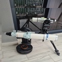
All the major components before final assembly

That is how the cold finger is introduced before insulation

Termistor (blue & white wire) and humidity sensor (green & brown wire) inserted for the gauge.

All cables tucked with main pcb assembled.

A sense of relief when the LCD comes on after the final assembly. ( yes it did not happen on first few attempt..lol)

Top view of the finished product. With clear view of the tempreature/humidity gauge.

Bottom view, with all the connection points. ( USB, power supply, bulb, dry air inlet )


![[smilie=good-job.gif]](./images/smilies/good-job.gif "good-job")

![[smilie=cool.gif]](./images/smilies/cool.gif "cool")
![[smilie=ahaaah.gif]](./images/smilies/ahaaah.gif "ahaaah")