2. The items were delivered without a user guide. iOptron should be sending out the user guide soon. iOptron has asked the first batch of testers to give feedback on their experience.
3. Packing and transportation box – Excellent.
4. Quality of product – Excellent physical condition.
5. Technical support from iOptron - Excellent, like for my previous iEQ45 and SmartEQ mounts.
6. My experience in setting up:
a. The setting up is straight forward for a GEM user. Some points to note are listed below.
b. RA and DEC locks – these are of a new design. The gear switch uses magnetic force and will be either at lock or disengage status. To lock, simply turn it to “engage” position. To unlock to “disengage”. CAUTION: Make sure you place your other hand on the mount head to support it when you set to “disengage” position because the mount head may fall down under gravity.
c. Fitting CW bar - The fitting of the CW bar needs a little more care and attention. At an optimal angle(shown in image below), it can be done relatively easily.
d. Enagaging the Gear. To operate the mount, the RA and DEC locks must be placed in OPERATIONAL POSITION(a term I coined) – where the gear switch is full engaged for mount movement under power. This is how Kevin at iOptron explains this position: “Turn clockwise to release the gear switch. Turn counterclockwise all the way out then turn clockwise half a turn to engage the gear.” CAUTION: It is important to set the knob properly to the OPERATIONAL POSITION to prevent damage to the gear when the mount moves under power. This is my interpretation of the “engage” and “disengage” positions and settings for operation:
(1) Engage position – the knob has to be turned fully counterclockwise, RA/DEC axis mechanically locked.
(2) Disengage position – the knob has to be turned fully clockwise, RA/DEC axis is released and free to move. This position is used for balancing.
(3) OPERATIONAL POSITION – the knob has to be turned clockwise half a turn from the “engage” position.
7. Operating Experience.
a. I did a one-star alignment on Sirius. Aligning was straightforward and mount goes to selected target reasonably accurate with a 24mm EP on a Megrez 90 scope.
b. PHD guiding – East-West/Norh-South calibration was a breeze. Clearing backlash was also straight forward. Unfortunately autoguiding failed because mount was drifting.
8. Major problem experienced - The mount drifts in RA in easterly direction in Track mode. When I switched off tracking (by pressing 0/Stop button on HC), object drift as expected in the Westerly direction. When I select Track mode (press 0/Stop button one more time), object drifts in the opposite direction to the East. It appears that the mount is applying the wrong correction to track the objects. I am working with iOptron to establish the cause of the problem. Investigation is in progress. I have used Sirius and Jupiter as test targets. With a 24mm EP on Megrez 90 scope, the drift across the entire field of fov of the 24mm EP is:
(1) Sirius – 8 mins 45 sec.
(2) Jupiter – about 9 mins 10 sec.
9. Firmware info on my 8407:
a. HC – 140119
b. Main – 140115
c. RA and DEC – 140121
---------------------------------------
Now the pictures and comments:
1. Shipment boxes.
https://dl.dropboxusercontent.com/u/207 ... _Mount.jpg
2. Contents of the mount box.
https://dl.dropboxusercontent.com/u/207 ... %20Box.jpg
3. Content of the mount box – items taken out.
https://dl.dropboxusercontent.com/u/207 ... %20box.jpg
4. Mount Head and CW – front view.
https://dl.dropboxusercontent.com/u/207 ... 20Head.jpg
5. Mount head – left side view
https://dl.dropboxusercontent.com/u/207 ... 20Head.jpg
6. CW bar.
https://dl.dropboxusercontent.com/u/207 ... %20bar.jpg
7. CW knob, mount head knobs and box keys
https://dl.dropboxusercontent.com/u/207 ... 0knobs.jpg
8. Power adapter
https://dl.dropboxusercontent.com/u/207 ... dapter.jpg
9. Hand controller cable and another cable.
https://dl.dropboxusercontent.com/u/207 ... cables.jpg
10. Hand controller
https://dl.dropboxusercontent.com/u/207 ... 8407HC.jpg
11. Battery cable and serial cable.
https://dl.dropboxusercontent.com/u/207 ... 0cable.jpg
12. CW
https://dl.dropboxusercontent.com/u/20796390/3_Cw.jpg
13. Tripod
https://dl.dropboxusercontent.com/u/207 ... Tripod.jpg
14. Install bolts for Mount head, remove the North reference pin - it is not needed.
https://dl.dropboxusercontent.com/u/207 ... 0bolts.jpg
15. Mount on tripod.
https://dl.dropboxusercontent.com/u/207 ... tripod.jpg
16. Mount on tripod – securing bolt installed (on leveling bubble side)
https://dl.dropboxusercontent.com/u/207 ... bubble.jpg
17. Mount on tripod – securing bolt installed (on compass side)
https://dl.dropboxusercontent.com/u/207 ... ompass.jpg
18. The lower red knob is for latitude setting adjustment.
https://dl.dropboxusercontent.com/u/207 ... 20knob.jpg
19. The infamous gear switch knob. (NEW Design)
https://dl.dropboxusercontent.com/u/207 ... 20head.jpg
20. Remember to tighten this back securing screw to prevent it hitting the mount
https://dl.dropboxusercontent.com/u/207 ... 20side.jpg
21. I find this is a good position to install the CW bar for the first time.
https://dl.dropboxusercontent.com/u/207 ... %20bar.jpg
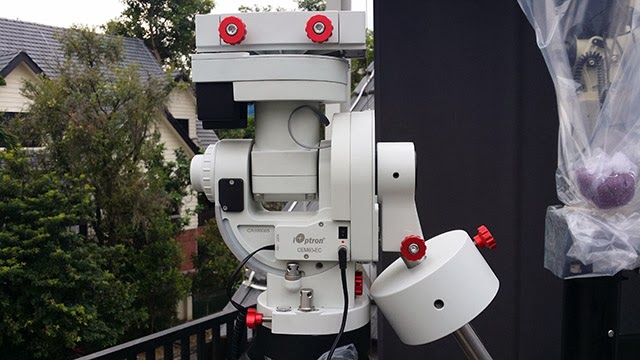
22. Right-side view of mount installed on tripod.
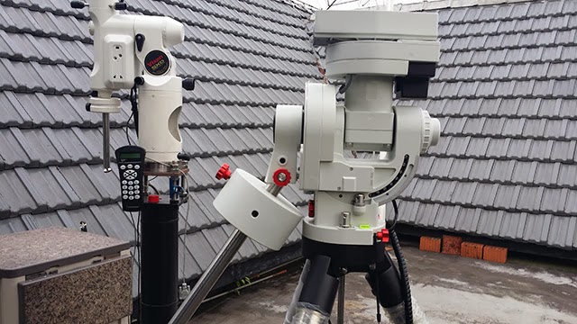
23. Left-side view of mount installed on the tripod.
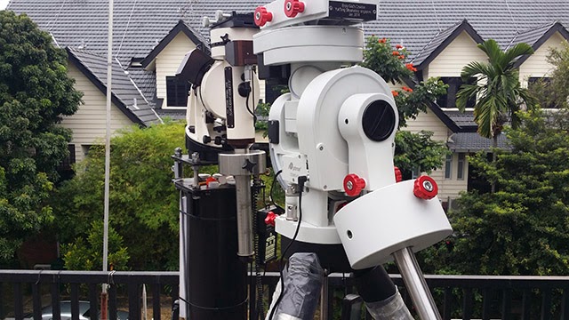
24. Front view of mount installed on tripod.
25. Megrez 90 on CEM 60
https://dl.dropboxusercontent.com/u/207 ... _CEM60.jpg
![[smilie=good-job.gif]](./images/smilies/good-job.gif "good-job")
