Been going through the telecompressor analysis and some accompanying testing recently (although still not sufficient to be convincing…clouds!), thought I may share with everyone some of my findings and investigations. Hopefully this will you to bear in mind when you plan to use a telecompressor for imaging with a refractor. The resolution is to find out if there is indeed an appropriate distance of optimization for the use of the Astro-Physics 0.75X telecompressor (27TVPH) besides achieving a certain compression ratio.
Some background info on the telecompressor: A telecompressor is used to make a refractor faster. It does flatten the resultant field to some extent but that is not the main objective, and should not introduce field curvature, but just attain a lower focal ratio number according to the spacing between the telecompressor and the imaging tool. Theoretically, the job of a telecompressor should just attain a certain compression ratio (the greater the compression ratio, the faster is the effective focal ratio) based on the distance variation of the spacing.
However, the following observation seem to indicate that the aberration profile changes with varying spacer distance and there appears to be still an optimal range of spacing distance to be used with the 27TVPH.

From the schematic diagrams above, it shows 4 possible configurations. It would be interesting if one could go through all 4 configurations and obtain an image profile of the resultant FOV. I have done this only for CONFIG 0 and CONFIG 3. CONFIG 1 is the configuration I have been using all this while previously and it does not display any edge distortions.
CONFIG 0 with the A1008-A spacer (2.5" in backfocus length) would technically achieve the greatest compression ratio (being the furthest from the telecompressor) and having the smallest illuminated circle of non-vignetting region. Consequently, CONFIG 3 will have the lowest compression ratio and hence the biggest illuminated circle of non-vignetting region. The compression ratio, illuminated circle, and effective focal ratios are all described in purple.
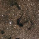
Next, I have also included the corresponding image FOVs showing the extreme corners at full resolution for the ST8300M with the CFW5 filter wheel in place.

The above shows the FOV based on CONFIG 0. You can see that there is asymmetric flaring of the stars comparing the left and right corners in general. The right corners seem to be visibly more pronounced and the flaring originates from the center point. Now if you look at the consequent image below (based on CONFIG 3), there is also asymmetric flaring of the stars comparing the left and right corners. Likewise the right corners show more pronounced flaring but interestingly, the "flaring point" originates from the opposite direction! Also, the degree of flaring is lesser (though in opposite direction) for CONFIG 3 then CONFIG 0. This seems to indicate that it is possible that at a certain spacing distance between that of CONFIG 0 and CONFIG 3, there would be a "sweet spot region" where one could image with the 27TVPH telecompressor successfully. Based on correspondence with another fellow imager having the exact same setup as myself, he is currently using CONFIG 2 with success (no edge distortion/flaring).

Note: Pardon the background image quality (lots of passing thin clouds and light pollution gradients, the idea is to focus on the star quality instead)
In conclusion, it is interesting to note that not only the telecompressor performance of the 27TVPH varies the compression ratio (with spacing distance), but the aberration profile changes accordingly too, which seem to indicate that it behaves like a field flattener somewhat, where it requires (instead of being specific) a "sweet spot" region of spacing where it will work optimal. Whether this is indeed true, we shall see! A3503 spacer ordered!
Note: Also added the file (below) to show the various components in the imaging train.

Stay tuned!